Sunday 18 September 2011

Brake Caliper Rebuild + Stainless Brake Line Swap (Part 1)

Hello everyone!
I'm going to be doing a series of posts on how I rebuilt the brake caliper on this 18 year old machine, and swapped out the tired old brake line for a Galfer stainless steel line. Hope you enjoy it!

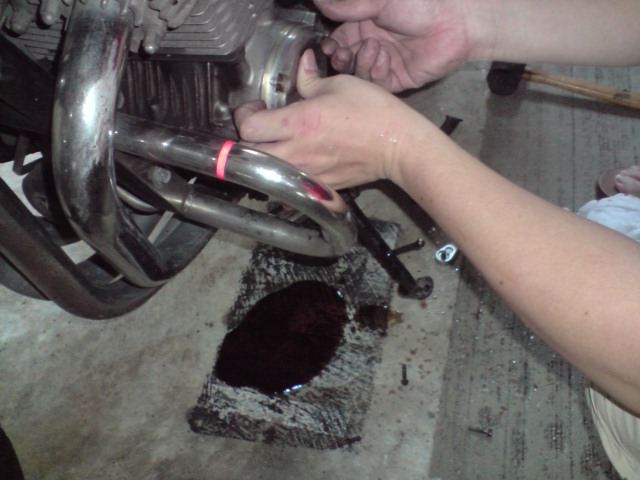
First thing I had to do is to get the brake caliper off the bike. Off with the mounting bolts. In no particular order, off comes the top one...

then the bottom one...
 Remove the cap that covers the pad pin.
Crack loose the pad pin bolt with an allen key.
On hindsight I would also strongly suggest that you also crack loose the screw that holds the brake hose onto the brake caliper. That screw is a tight one to remove, and if you try to loosen it after removing the caliper mounting bolts, you'd need a vice or it's not going to be easy.

Just crack it open a tiny bit so that it's easier to remove later, but not so much that the brake fluid is going to leak out.

Here I unscrew the pad pin all the way out.
And then you just pull it out.


You'll notice that the pad pin is badly encrusted with years of built up crud. We'll deal with that later. It's no wonder the brakes aren't working well, the pads can't slide smoothly over the pin when it's badly covered in crud.

And you just pull out the pads. These still have a lot of meat left on them, so I'm going to clean them and reuse them.
This is how the caliper looks. See how clean and shiny it looks.

See those two round things in the picture below? Those are the brake pistons. When you squeeze the brake lever, you transmit the force applied to the hydraulic fluid (that will be your brake fluid) that's in the master cylinder (that's the black boxy thing with brake fluid on the right side of your handlebar).

Since brake fluid is not compressible, it transmit that force down the brake hose and into the brake caliper. There are hollow chambers and passages cut out inside the brake caliper where the brake fluid from the brake hose can travel into, and it finally goes into two hollow chambers behind these pistons.

The brake fluid then forces these pistons to move out from the caliper body and push into the back of the brake pad, which then squeezes the brake disc which gives you the friction needed to stop the bike.
The normal way that you would go about removing these pistons is to use a hose attachment connected to an air compressor to pump air into the hole where the brake hose goes into, and that will force the pistons out.

If you're going to do that, make sure you put a piece of wood on the opposite end of the pistons to catch it, because it's going to come flying out at great force. Make sure no part of your finger is in there when you do it.

Since I don't have access to a compressor, and can't justify buying one just to do this job, I had to lie in bed many nights coming up with a plan. An evil plan.

I've heard of people using a grease gun to pump grease instead of air into the caliper to get the pistons out, but I really hated the thought of doing that. I can't imagine how I'm going to clean out all the grease from all the passages inside the caliper later on. That seemed an even more daunting task to me then the task of removing the pistons themselves.

You might be thinking to yourself, why not just use the brake lever and brake fluid to force the pistons out? The problem is that the pistons are not going to be forced out at equal rates, and once one piston comes completely out and the brake fluid faces no resistance in that chamber, it's all going to flow out from that chamber and you would lose all pressure in the system, and won't be able to get the other piston out either.

You will not be able to pull these pistons out by hand. Not a chance. Anyone who tells you that you can do that is either:

A) King Kong
B) Chuck Norris
C) Lying through his teeth
D) Parks his bike in a showroom and never rides it

Anyhow, there's no chance I'm going to have any chance pulling even a partially out piston by hand.

Well, after many nights lying awake in bed, I finally came up with a plan. As far as I know, I've not seen this done before, but I'm sure someone somewhere must have thought of it. Just that I haven't seen it anywhere on the web.

What is it? What's the plan? Let's find out in Part 2....(ducking and running)

Thursday 15 September 2011

A cool "Tips and Tricks" ebook

Came across this ebook on the web called "Workshop Secrets". It brings back memories of the many pleasurable late nights I spent devouring all the secret tricks and techniques that mechanics use in the "Haynes Workshop Manual." (although many of the tips in that book are now kinda old and obsolete)

I looked through the points and oh, I'm sure these are all situations most of us have all been through before!


Listen to this...
  • What do you do when you drop a bolt someone into your vehicle, and you can't reach it? (I'd grab my extendable Craftsman magnetic probe). 
  • It goes on to say, what if the object is made of brass, aluminum or plastic? (Well that'll be a pain.....)
  • How to make sure you never forget when an oil change is due. (I think this one will really be useful for me.)
  • Easy way to fit wheel bearings (You mean there's another way other than pounding it in with a huge hammer? I'm guessing its probably to use heat.)
  • How to stretch strong springs for easy fitting. (Ouch.)
  • Greatly increase the holding power of self-tapping screws.
  • Ensure brake shoes stay clean when fitting them.
  • How to remove bushes from blind drillings. (Even with a slide hammer, this one has got to be a real pain.)
  • Simple way to ensure bolt/nut doesn't drop out of socket.
  • How to guide bolt into place one handed.
  • Etc. etc...
Check it out and let me know what you think. I think it's going for $17.

Click here to check it out.

Tuesday 28 June 2011

Mistake in compression test

Hi,
I'd just like to highlight a mistake I made in the compression test. I was re-reading through the manual again and happened to come to the section on the compression test. I noticed that I missed out something.

The manual says to hold the throttle wide open while cranking the engine over. I forgot to do that.

Being curious, I wondered if it made a difference, so I removed one plug and hooked up the compression gauge and gave it a try. I got a reading of 150-160PSI (contrast that with past readings of 90 - 100PSI). So apparently it does make a big difference.

Thursday 9 June 2011

Timing Check (That Didn't Go As Planned...)

I got me a timing light because the ignition timing check was listed as part of the tasks to do in the maintainance checklist....


The hardware is simple. There's the timing light itself, and then there's the positive and negative cables that you hook up to the battery to provide power. The last wire with the red box-like thing is the induction clamp. More on that later.

A close shot of the light itself. It's a cheap one I got from HarborFreight.

Hooking it up was simple. Just connect the red clamp to the positive post of the battery, and the black clamp to the negative post.

After that, hook up the inductive clamp to the spark plug wire going to the #1 cylinder's plug. The #1 cylinder is the leftmost cylinder on the Nighthawk.

This is how it works, as I understand it. The positive and negative cables provide power to the timing light for the light itself. The inductive clamp is the one that times when the light goes on.

Whenever a current passes through the spark plug wire to fire the plug, the inductive clamp picks up that current in the wire and triggers the timing light to turn on. So seeing the light going on and off is somewhat equivalent to being able to "see" when the plug itself fires.

So how do we use this thing that looks like Han Solo's lazer blaster to check the ignition timing? Well, let's talk about theory or a minute, shall we?

The petrol (or gas) in the cylinder needs a certain amount of time to properly combust, and this time is more or less constant, as determined by the laws of physics. (Of course it's not that simple in real life, what with compression differences and difference in air flow and all that). When the engine speed is slow, you can ignite this mixture when the piston is almost at Top-Dead-Centre (TDC).

Obviously, when the engine speed increases you can't still be firing the mixture at near TDC, because the mixture needs approximately the same time to burn, whether the engine is turning at 900rpm or at 6,000rpm. You'll have to ignite the mixture earlier, so that the power is generated when the piston is on its downstroke (or power stroke).

Controlling when the spark fires is what's known as ignition timing. In older bikes, this used to be controlled by what's known as mechanical "points", and that system was notoriously unreliable because the points wear out.

The next generation of motorcycles have an ignition timing module, which is a little computer that calculates when to fire the plugs based on simple things like engine RPM.

The really modern machines have an ECM (engine control module) that takes in a lot of inputs from sensors like air temperature (to calculate air density), throttle position, engine speed, presence of engine knock and so on to determine when exactly to fire the plugs so you get maximum power or a cleaner running engine, whichever the ECM was tuned for.

I'm a simple backyard mechanic and can't deal with all that complexity, so I'm thankful for the Nighthawk.

On the Nighthawk, the ignition module is not adjustable. So all you can do is check whether the thing is operating as it should or not.

So on to the check. First you have to remove the timing cover, its just held on by 4 screws. Make sure you put the bike on the mainstand first, because there's oil in there.

Can you see the triangle circled in red? That is your reference mark. The round spikey circle in the centre (pointed to by blue arrow) is connected to the crankshaft and it will spin when the engine is running. There are reference marks printed on it that is supposed to line up with the arrow when the #1 plug fires.

My apologies for not taking a close up of those reference marks. It was getting dark and I was kinda rushing through this, not a good idea. But the idea is this. You point the timing light at that arrow, and when the plug fires, the light will shine and you will be able to see if the marks on the spikey circle lines up correctly. It works because of the way our eyes work, something called "persistence of vision" or something like that.

When the bike is idling, the reference mark (the arrow thinggy) is supposed to line up with one of the marks on the spikey wheel. When you rev it up to 3,000rpms, you'll see the mark "rotating" on the wheel as the timing advances to fire the plugs earlier.

Well I didn't really take good pictures for this job and you'll soon see why. But first, I hook up the induction lead to Han Solo's blaster.

This is when things get fun. I start the engine and...
Oil starts splattering and gushing out. Bummer! Well, I thought since I've already come that far, I might as well tough it out and get it done. Revved the bike up to 3,000rpms and found out it wasn't a good idea. I had warm oil splattering all over my face, arms, everything. Gives a whole new meaning to the term "oil bath".

So I quickly grabbed the timing cover and pressed it against the engine and turned the bike off. Decided to call it a day, and admit defeat.

Splattered shorts. It might catch on as a macho fashion statement, who knows.

Well, things didn't go as planned, and that's how these things turn out from time to time. You go back, sleep on it, think about it, and come back and try again another day.

I realized that the design of the timing cover sucks on the Nighthawk, probably because it wasn't designed to have the timing checked. Most other bikes have a small peep window for this, to prevent this from happening.

There are two possible solutions for the Nighthawk if I were to do this again. The first is to get another cover and cut off a small window on the top that will enable me to see the timing marks.

The second was recommended by someone on a forum, and that's to try using clear plastic wrap to wrap the whole thing up when doing the test. I don't know if it'll work or not, the plastic might melt, but it sounds plausible. If you try it, let me know how it works out.

So that's it for this edition folks. Keep at it, and use your tools!

Saturday 21 May 2011

Performing a compression test (Part 2)

My apologies for the longer than expected delay to part 2. Had been really busy with work recently, and still am, but I'll try to update this blog regularly.

In our last post, we stopped after we removed the plugs. The next thing we want to do is to apply some anti-seize on the threaded end of our compression tester hose.
Next we screw it in by hand into the first cylinder. It should go in quite easily if the threads are in good condition.
Next, you want to make sure you screw it in there really snug, so grab the knurled portion on the top of the hose and give it a good firm turn. Here's the knurled portion of the hose that I'm talking about.
Giving it a good turn till it'll go no more...
Next, we connect the hose to the compression gauge. For this model of compression gauge, I need to pull down the brass ring on the hose connected to the gauge side, and then slip it over the hose that connects to the engine.
In it goes, and I give it a tug to make sure it's snug.
Next, get yourself a piece of paper and a pen. Draw a table with two rows and four columns. The four columns will be for recording the compression readings of the four cylinders, one to four.

The two rows are for recording two runs of this test, one for a dry test, one for a wet test. First we'll do the dry test, and we'll talk about the wet test later.

Flick the Run button to "OFF" and then hit the starter. This turns the engine over, but the coils won't fire.

EDITED TO ADD: I made a mistake in my initial test. I forgot one very important step, and that is the open the throttle all the way. It will make a huge difference to the PSI readings, so make sure you fully open the throttle before cranking the engine over.

 
I generally hold the starter for 5-8 cranks, but no more than 8 cranks. There's a lot of current passing through the cable to the starter when you do this, so you don't want to hold it too long as the heat will fry the cables. After each cycle, wait awhile to let the cables cool down, before you repeat.
 
When you press the starter button, you'll hear the engine cranking over. Maybe something like this, "eeee........eeee.....eeee....eeee..."

You can tell I'm not to good at sounds, but you get the idea. I listen for 8 of those "eeee" sounds, while watching the needle on the gauge reading. Sometimes, you need to repeat this two or three cycles for the needle to hit its maximum reading. Now do you see why we need that battery charger?

Once the needle doesn't go up anymore, write down the reading in the table I told you about earlier. This goes under the "Dry run" row. The reading for cylinder #1 is 105 PSI.

After you're done, use the air-release valve on the hose to release the compressed air in the system before unplugging the hose.
Next you want to disconnect the hose, and then unscrew the threaded portion from the cylinder. The next test you're going to do is a wet test. To do this, you're going to squirt some clean engine oil into the cylinder before repeating the compression test again.

The purpose of doing this is so that the oil will help seal the piston rings against the cylinder walls. What we're trying to do is to find out where our loss of compression is coming from, either we're losing compression through gases escaping through the piston rings, or gases escaping through the valves because they're not sealing properly.

By squirting the oil into the cylinder, we're trying to eliminate one variable in the equation: gas escaping through the rings. If the readings increase significantly after we add oil, we know the piston rings are not sealing properly. If the readings stay about the same, most probably we're losing compression through the valves.

There are exceptions to this however, and it's important to realize this is not fool-proof. One example is if the gaps in the rings align and allow the gasses to pass through. I've seen this happen in a car engine once, so it's possible.

A more accurate way to troubleshoot where the leak is coming from is to do a leakdown test, but you'll need an air compressor for that.

Back to our wet test. If you have an oil can, squirt 2-3 squirts of oil into the cylinder. Otherwise do what I did. Just use a straw to draw up some engine oil from a bottle...
and release it into the engine.
Repeat the compression test, and take the wet reading, and write it into the table.

After this, just repeat this for all the cylinders. I'm only going to show the pictures and readings for the dry test.

Cylinder #2:
Reading for cylinder #2 is 110 PSI.

Next up is cylinder #3:
Reading for cylinder #3 is 100 PSI.

Finally, cylinder #4.
 Reading for cylinder #4 is 85 PSI. That's a bit lower than the rest.

The readings of the wet test didn't really increase compression by much, except in cylinder #2, which went up about 10 PSI, which isn't really that significant I think. However, they're all below the minimum specification. The allowable range is 142 - 199 PSI, so if these readings are accurate, that means this engine needs a rebuild

Frankly, I'd want to run this test on a bike with a known good engine and see what kind of readings it gives me, just to confirm that the gauge is reading correctly.

Well, that completes our compression test. All that's left to do now is to put all the plugs back and button up everything else.

The use of a torque wrench is highly recommended for this, because the cylinder head is a critical component and it's aluminum, so you don't want to overtighten anything in there.

Mine's a Craftsman. This model is the microtork, and it has worked fine for me so far (about 10 years of occassional use), and has a very nice action. However, avoid their "digitork" range, that one crapped out on me in weeks. It's a complete waste of money.

I torque down each of the plugs to their specified torque setting, and then I'm done.

So give it a try, and see how your engine's doing. Happy wrenching!

Saturday 7 May 2011

Performing a compression test (Part 1)

Hello!
Today we're going to do something exciting. We're going to find out the true condition of the engine, and we do that by performing a compression test.

The engine is nothing but a glorified air pump. In order for you to get maximum power to the wheels, your engine needs to have an airtight seal. That means that no gases are leaking past the valves (both intake and exhaust) and no gases are escaping past the piston rings.

In order for us to test how well the engine is sealing, we need the help of a tool. We need a compression tester.

Here's what it looks like.
The attachment hoses on the left have different sized plugs that allow you to do this test on different types of engines. The one that came with this kit comes with attachements for 10mm, 12mm and 14mm holes. The hole on the Nighthawk is 12mm.

I think most cars use either 14mm or 18mm.

On to our test. In order to properly perform this test, you need to warm up the bike really well. This is because the pistons need to be heated up to their proper operating temperature before they'll seal the cylinders well. From what I read, pistons are actually more oval in shape when their cold, and they only become fully round when they reach their proper temperature.

So to avoid false readings, warm up the engine really well. I had to do this test a second time because I didn't warm it up properly the first time, and so doubted my readings.

First you need to remove the seat, the fuel tank and the side panels. As I've already gone through this in detail in previous posts (Carb Sync), I won't be going through these steps again.

Next you need to hook up a battery charger to the bike's battery. You'll be using a lot of battery juice for this test as you'll be cranking the engine over repeatedly, so the charger prevents the battery from getting drained.
When hooking up a charger, always turn the mains off first. Hook up the red clip to the positive post of the battery first, then hook up the black clip to the negative post. Preferably you should hook the black clip not on the battery post itself, but on the engine or a bare part of the frame (ground). This is the safest way because if there's a spark for any reason, it happens away from the battery. But I did it the easy way because the cable wasn't long enough.

Before you remove the plugs, take some masking tape or sticky tape and label the plug wires with the numbers #1, #2, #3 and #4 so you know which plug wire goes to which plug. The leftmost cylinder is #1.


I took this opportunity to check that the order of the plug wires were ordered correctly. The Clymer manual has the order wrong, so take note of that. The Honda manual gives the correct ordering. This is the correct order:


#1 goes to the Right Bottom coil

#2 goes to the Top Left coil

 #3 goes to the Bottom Left coil

 #4 goes to the Top Right coil

The plugs and cam cover will be hot so make sure you wear work gloves. I used these gardening gloves, which are cheap and work very well to insulate against heat.

When removing the plug wires, do not pull on the wires themselves. Grab the plug cap and give it a smart tug upwards.

 Once the caps are off you'll see the spark plug sitting in the engine head.

 Next you'll need to remove all the spark plugs. Before you do that, you have to blow out all the dirt around the spark plug holes. There will be a lot of dirt and crud and sometimes even small pebbles lodged in there, because the area is so recessed, so make sure you do this thoroughly. If any dirt falls into the engine, it'll damage the engine.

If you have an air compressor, that'll be the best tool for the job. I didn't so I just used a long straw to blow around the area. Wear a face mask or at least close your eyes when you do this, because stuff will get blown into your face.

You'll need an 18mm long socket and a long extension to remove the plugs.
Crack open the plugs half a turn, then stop. Pick up the straw and start blowing around the plugs again. Make sure it's totally clean before proceeding.

Remove all the plugs. We want to reduce the amount of resistance that the engine will face when we crank the starter. This will allow us to get to our reading faster and drain the battery less. 


 All four plugs out.

I'm not sure when these plugs were last changed, but the electrodes looked ok. The carb mixture setting looks to be ok too,  from the look of the plugs. If you're going to reuse the plugs, try to keep them in the order in which you removed them, so that you can put them back in their original cylinders. These are going into the trash though. I bought new ones.

Ok, we'll stop here for Part One. I'll update the rest when I get more time. I have more exciting stuff coming up, including an ignition timing test that didn't go as planned, a stainless brake hose swap, brake caliper rebuild and swapping out the rear shocks.

Please follow this blog to be informed of new updates, use your tools and happy wrenching!